


The logic of the Gamma 10 computer is organized in fairly large single-sided printed printed boards with 44 gold plated side contacts. Unique about the boards of the gamma 10 (and gamma 55) computer boards, is that the larger boards can contain up to 8 sub-boards that are mounted perpendicular. This allows the construction of fairly complex logic on these boards, and avoids the necessity of extra wires to make crossings otherwise needed when using single layered boards.

The boards are mounted per 20 pieces in a rack, and there are about 25 racks in the gamma10. This makes for about 500 boards, with on average 8 transistors per board: i.e., 4000 transistors.
The power supply is -12 V (primary power, 12.5 A for the smaller gamma 55), +10 V (negative bias to cancel the voltage drop over the diodes, 2 A for the gamma 55) and -45 V (power for relays and actuators, 4A for gamma 55).
Two nice boards are shown here. First a shift register board using JK flipflops. I modified these boards to make a counter to build a synthesizer. Note the 8 contacts on the top side of the board: these are test pins, allowing easy measurement of signals within the computer.

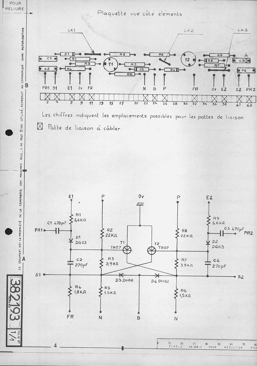
From Kelkheim I got the schematics, first the sub-board containing one flip-flop each. The input capacitors store the incoming data during the clock pulse, allowing a shift register with just two transistors per bit.
This is the block schematic - note the connection to the test pins 1-8:

A second nice boad is the "plaque de detect de inegal", or comparator board. This board has flip-flops as inputs.:

And again is here the schematic:
